From Feature Tetris to Full Power – The UV-K5 Flex PCB Brain Hack
The Quansheng UV-K5 makes you play firmware feature Tetris with its tiny MCU. In this project, we perform some embedded brain surgery—replacing it with an STM32 via a custom flex PCB for more flash, RAM, and possibilities.

When I earned my amateur radio license a few years ago, one of the first handheld radios I picked up was the Quansheng UV-K5. It was affordable, surprisingly capable, and, best of all, it had an open-source firmware community. For a tinkerer like me, that made it irresistible.
It's possible to tweak the firmware and add features, but there was a major limitation! The radio’s stock MCU only had 64 kB of flash memory, with about 4 kB already used by the bootloader. This forced users to build firmware versions with specific feature sets, like playing Tetris with functionality. Sure, that worked, but wouldn’t it be way more fun to have all the features on a single radio?
Of course it would ( ๑‾̀◡‾́). So, I set out to see if I could replace the official MCU with something more powerful. That’s how my little project, which I call nanoimp (short for “nano implant”), was born.
Research: Finding the Right Brain!
I began my research by going over the Wiki created by ludwich66 on GitHub. My first step was to identify the radio's main controller, which turned out to be the DP32G030, a chip from a Chinese manufacturer.
Initially, I hoped to find a pin-compatible MCU from the same company with more flash memory and RAM, but that proved to be a dead end. The DP32G030 seemed to be a budget-oriented, general-purpose MCU with no direct, high-capacity replacement.....oehh..shame...but okay, so what now?

Alright, maybe not with a hammer, but new "silicon brain" would do the trick. As I shifted through the controllers manual, the name DP32G030 seemed oddly familiar. It was strikingly similar to the STM32G0 family, both share the Cortex-M0+ core and feature nearly identical peripherals.
I turned to STM’s product search tool, plugged in the necessary parameters, and out came the STM32G0x1 series. It had all the required peripherals and ample storage. The primary obstacle was the incompatible pin out, the Chinese controller had a very different pin arrangement and even more GPIOs packed into its LQFP32 footprint compared to similar STM32 controllers.
With no pin compatible alternative, I needed to somehow remap the signals from the radio to the adapter. In the retro gaming community, flexible PCBs are often used to fit modern hardware into tight, classic consoles. I realized the UV-K5 had a small gap between the main PCB and the aluminum back-plate. I could replace the original chip with a tiny "brain implant" of my own design, built on a thin flexible PCB.
Creating the Proof of Concept Implant
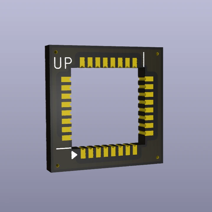
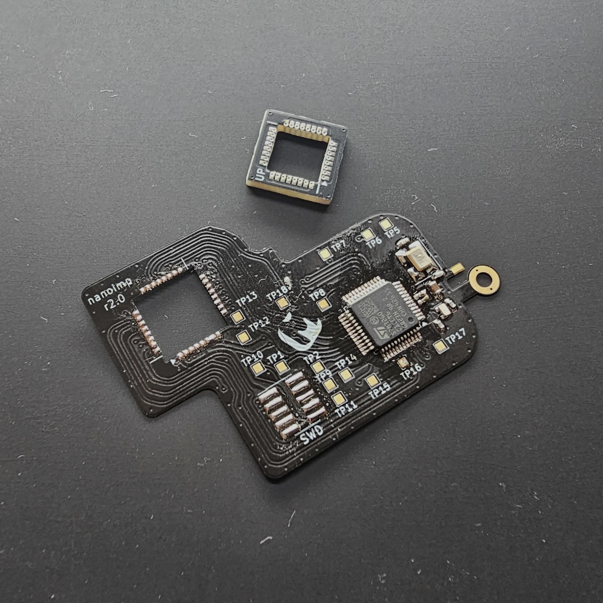
Finally, for the silicon brain, I chose the STM32G0C1CET, which is a 48-pin controller with LQFP footprint, 512 kB of flash and 144 kB of RAM. It had all the peripherals the original controller used, including more uncommon AES peripheral used by the original radio.
First, I mapped all the signals that the DP32G030 had, e.g. SPI MISO, PWM etc, using the wiki, schematic and firmware code. This was critical to ensure I didn’t miss anything. Next, I matched the DP32 signals to the STM32G0C1 pins. This was the trickiest part as I needed to ensure the pin-out wouldn’t make PCB routing a nightmare. Once that was done we created a simple schematic and PCB design in KiCAD.

With the design ready, we ordered the flex PCB from JLCPCB. I’d never worked with flex PCBs before, so this was a leap into the unknown. While waiting for the boards to arrive, I started writing driver code to replace the old DP32 firmware with STM32-compatible versions. I based my firmware version on armel's custom firmware that has been the most active. I dug into the datasheet and created bare-metal drivers to get a head start.
When the board finally arrived, it was so thin, almost fragile. I soldered the STM32G0C1 and SWD wires for flashing and debugging. Since I forgot to order SMD decoupling caps, I improvised with a through-hole ceramic cap. Hacky? Yes. But it fit.

Preparing the Radio
I disassembled the UV-K5 and removed the PCB, which was a little inconvenient to be honest, as there where short wires for the speaker and hidden screws behind the screen. Unfortunately, I don’t have photos or video of this process, but I hope you can imagine the process.
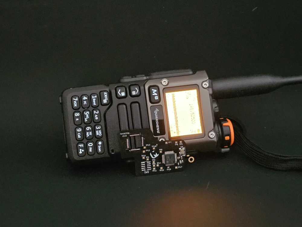
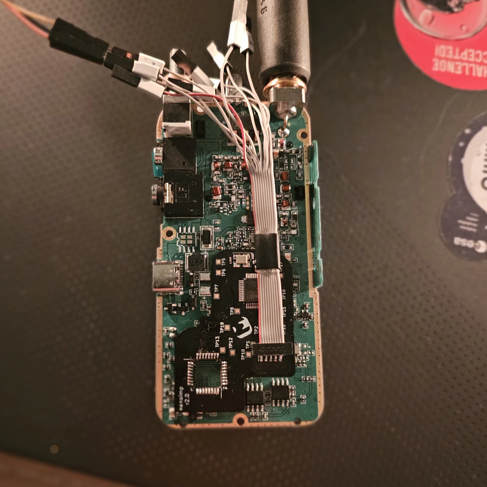
I secured the PCB in my soldering fixture and removed the DP32G030 using a hot air gun and tweezers. After cleaning the pads, applying a little solder, I soldered the flex adapter to the board. This was trickier than I anticipated, but I managed. Here is the result.

A quick check with the multimeter confirmed no shorts, after that it's time for the first test.
First Run: The Moment of Truth
The UV-K5 has a white LED near the power button, which made for a perfect initial test. Blinking a LED is the "Hello, World!" in embedded programming (˶ᵔ ᵕ ᵔ˶). I set up the debug connection using OpenOCD and a CMSIS-DAP probe and flashed a simple LED blink program.
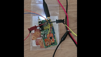
Success! The debug session worked, and I could flash code to the STM32. Next, I updated the pinmap in the original firmware and implemented the necessary drivers for the STM32. After some tweaking, the screen and buttons sprang to life.

Lessons from the First Prototype
The initial flex PCB proved the concept: brain surgery on embedded systems is possible. But the thin, fragile board struggled with mechanical stress. Pressing buttons or moving the board sometimes broke traces, halting development.
While there was progress, it was clear that the flimsy flex PCB wouldn’t hold up for long-term use or on field testing. We needed a more robust design that could survive outside the lab.
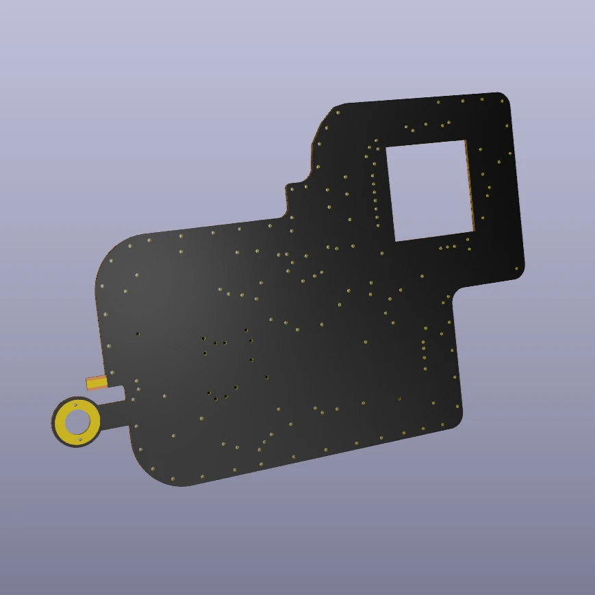
The Birth of Mk II: A More Robust Board
To improve the flex PCB, we needed to address several issues from the Mk I board:
- Better flex design: Rounded traces instead of sharp angles, to reduce stress as sharp angled traces were prone to break.
- Improved durability: A slightly thicker flex PCB would survive repeated handling and installation during the development phase and be more robust during on field testing.
- Improved adapter connection: The adapter pads and the pads on the PCB should be on the same height to reduce unnecessary stress to the flex board.
- Test points: Unused pins would be broken out as test points for future experiments or as additional debug options.
- Optional extras: Pads for external clocks, replace soldered debug wires with a robust debug header.
- USB potential: The STM32G0C1 has a USB peripheral, and the UV-K5 already has a USB-C port (currently only for charging). With the right wiring, maybe we could add real USB functionality down the line?
With these changes, the nanoimp Mk II was born, a redesigned flex PCB ready for a field day.

After a new round of ordering, I could finally install the Mk II. I flashed the latest firmware that I had been working on, with most drivers working at that point. It was another success, but this time, the platform was far more stable!


Next Steps
This is just the beginning. With a robust flex PCB and a powerful MCU, the possibilities for the UV-K5 are wider than ever. Stay tuned for updates on USB support, further optimizations.
Prototyping in an Hour: A Small PCB and a Quiet Shift in Embedded Work
Designing and ordering a custom PCB in under an hour — a reflection on modern KiCad workflows and how rapid prototyping has quietly changed embedded development.
Remote View Raspberry Pi Camera Stream with Docker
Learn how to containerize the Raspberry Pi Camera Module using MediaMTX and Docker for low-latency remote debugging and visual feedback directly in VS Code.
How to Move RTT to a Custom RAM Section in Embedded Rust
Learn how to place RTT buffers and the control block into a fixed RAM section in embedded Rust. This guide covers linker script changes, custom RTT initialization, and setting up a reliable RTT print channel.
Whether you're building something new, fixing stability issues, or automating what slows your team down — we can help.